
- Official UK and Ireland channel partner
- UK technical support available
- Model selection and configuration support
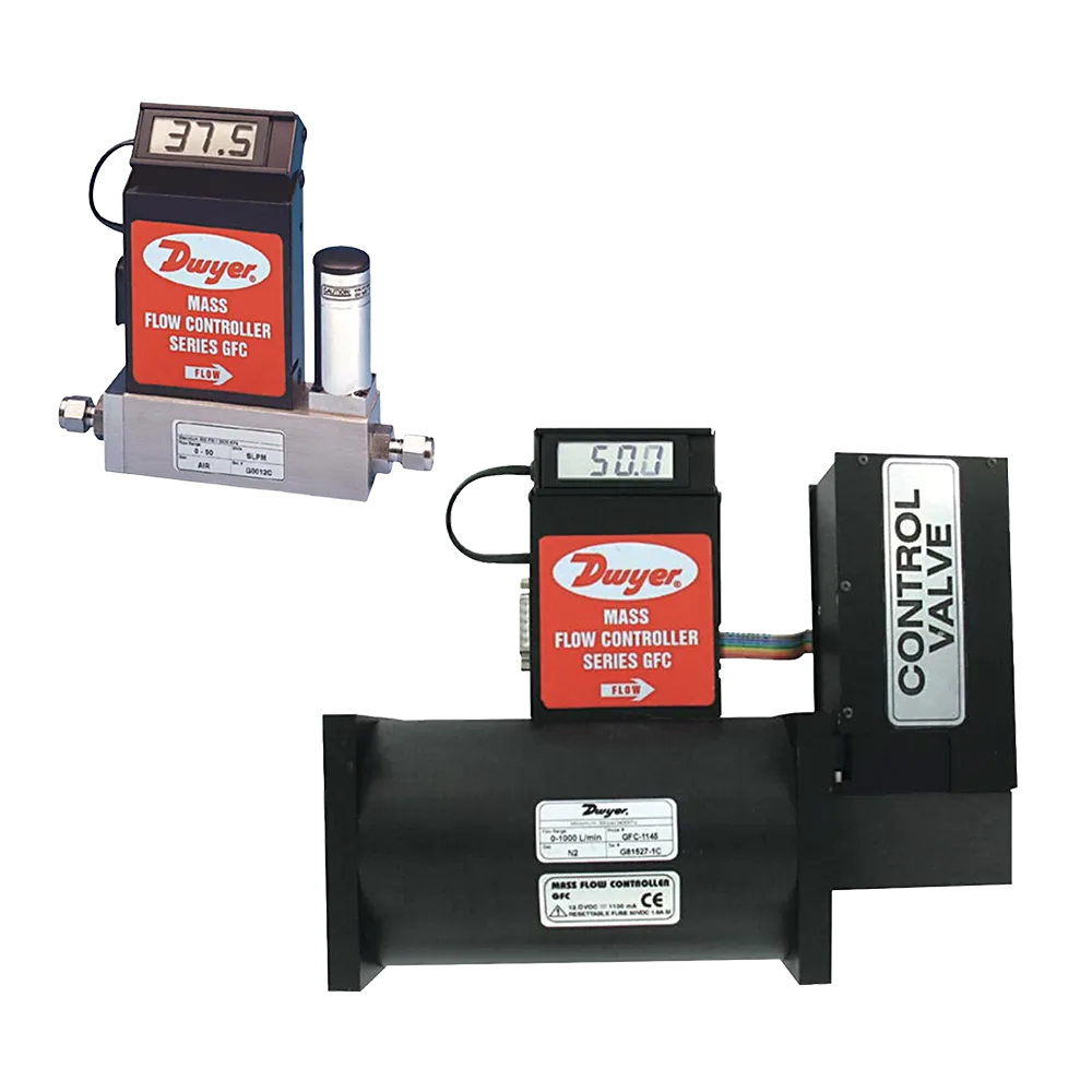
Dwyer GFC Gas Mass Flow Controllers
Closed-loop measurement and control of clean-gas mass flow from 10 mL/min to 1000 L/min, with local or remote setpoint control.
Key highlights
- Closed-loop control: Integrated measurement, PID electronics and valve control
- Flow range: 10 mL/min to 1000 L/min full scale
- Setpoints: Local potentiometer, 0-5 VDC or 4-20 mA
- Valve options: Solenoid or motorised, model dependent
- Calibration: NIST-traceable certificate included
The Dwyer Series GFC is a gas mass flow controller family for measuring and regulating the flow of clean gases. A straight thermal sensor tube, restrictor element, integral valve and PID electronics work together to maintain the selected flow rate.
The controller continuously compares measured flow with the setpoint and adjusts the valve to correct deviations. Setpoints can be established locally or supplied remotely as a 0-5 VDC or 4-20 mA command.
Flow range, calibration gas and valve type must match the application. Current catalogue models cover 10 mL/min to 1000 L/min full scale. Lower and medium flow models use a solenoid valve, while the X143-X145 high-flow groups use a motorised valve.
Construction, process connection and pressure limits vary by model. Aluminium-family and stainless-steel-family configurations are available, with connection size increasing through the range. The gas, operating pressure and wetted-material compatibility should be established before selection.
Display-equipped versions provide local actual-flow indication, while 0-5 VDC and 4-20 mA signals support integration with monitoring and control equipment. Typical duties include gas blending, film deposition, vacuum processes, coating equipment, burner or furnace systems and general process-gas control.
Key Features
- Closed-loop thermal control: PID electronics compare measured mass flow with the setpoint and adjust the integral valve
- Model-matched valve: Solenoid valves serve lower and medium flow groups; X143-X145 models use motorised valves
- Flexible setpoint control: Built-in local potentiometer or remote 0-5 VDC / 4-20 mA command
- Actual-flow indication: Optional 3.5-digit LCD tilts through 90 degrees for local viewing
- Analogue integration: Linear 0-5 VDC and 4-20 mA flow outputs, with signal calibration selected for the application
- Range and material choice: Current aluminium-family and stainless-steel-family models span 10 mL/min to 1000 L/min
- Traceable calibration: NIST-traceable calibration certificate supplied with the configured controller
Specifications
| Measurement and Control | |
| Function | Clean-gas mass flow measurement and continuous closed-loop control |
| Measurement principle | Thermal mass flow sensor with straight sensor tube and restrictor flow element |
| Control method | PID electronics continuously compare measured flow with the setpoint and adjust the integral valve |
| Valve types | Proportioning solenoid valve through GFC-1142/2142; motorised valve for GFC-1143/2143, GFC-1144/2144 and GFC-1145/2145 |
| Flow ranges | 0-10, 0-20, 0-50, 0-100, 0-200, 0-500 or 0-1000 mL/min; 0-2, 0-5, 0-15, 0-30, 0-50, 0-100, 0-200, 0-500 or 0-1000 L/min |
| Reference range conditions | Equivalent nitrogen flow at 21°C (70°F) and 760 mm Hg |
| Turndown ratio | 40:1 |
| Accuracy | ±1% of full scale for models through GFC-1142/2142. For GFC-X143, X144 and X145: ±1.5% of full scale over 20-100% of range and ±3% over 0-20% of range; the operating manual also references an enhanced-accuracy option |
| Repeatability | Official sources list ±0.25% to ±0.5% of full scale; confirm the applicable figure for the selected model |
| Control response | Approximately 1 second for GFC-1100-09/2100-09, 2 seconds through GFC-1142/2142, and 5 seconds for GFC-X143, X144 and X145; stated to within ±2% of set flow over 25-100% of full scale |
| Media, Materials and Calibration | |
| Service | Clean gases compatible with wetted parts; not suitable for liquids |
| Gas calibration | Specify the calibration gas, full-scale range and engineering units; published gas K-factors are approximate |
| Calibration certificate | NIST-traceable certificate included |
| GFC-1XXX material family | Anodised aluminium, brass and stainless-steel wetted components with fluoroelastomer seals; confirm exact alloy and seal compatibility for the selected model |
| GFC-2XXX material family | Stainless-steel wetted components with fluoroelastomer seals; confirm exact alloy and seal compatibility for the selected model |
| Optional seals | Buna-N, EPR and FFKM seal options are referenced in the operating manual; confirm current availability and gas compatibility |
| Oxygen service | Confirm application suitability and specify oxygen-cleaning service where required |
| Process Conditions and Installation | |
| Process connections | 1/4 in compression for ranges up to 50 L/min; 3/8 in for 100 and 200 L/min; 1/2 in for 500 L/min; 3/4 in for 1000 L/min. Confirm the exact 1000 L/min connection because current official sources differ between FNPT and compression |
| Maximum gas pressure | 1000 psig (68.9 bar) through GFC-1142/2142; 500 psig (34.5 bar) for GFC-X143, X144 and X145 |
| Maximum differential pressure | 50 psid (345 kPa) for most models; 40 psid (276 kPa) for GFC-1142/2142 |
| Temperature limit | 0 to 50°C (32 to 122°F) |
| Maximum particulate size | 5 microns; contaminated gas must be filtered before entering the controller |
| Maximum internal valve leak | 0.5% of full scale; Series GFC is a regulating controller, not a positive shut-off valve |
| External leak integrity | 1 x 10⁻⁹ scc/s of helium to the outside environment |
| Installation orientation | Gas path horizontal within ±15 degrees; recalibration may be required for a different orientation |
| Flow direction | Install in the direction indicated by the arrow on the controller |
| Warm-up time | Minimum 15 minutes before checking or adjusting zero |
| Signals, Display and Power | |
| Local setpoint | Built-in potentiometer |
| Remote setpoint command | 0-5 VDC or 4-20 mA; 4-20 mA input requires a three-wire sourcing device and presents 250 ohm input impedance |
| Actual-flow outputs | Linear 0-5 VDC and 4-20 mA |
| Output loading | 0-5 VDC: 1000 ohm minimum load; 4-20 mA: 0-500 ohm loop resistance, sourcing output for a passive load |
| Signal calibration | Default input/output calibration is 0-5 VDC. The manual states that using 4-20 mA indication without the corresponding calibration can increase total output-reading uncertainty to approximately ±2.5% of full scale; specify 4-20 mA calibration when required |
| Local display | Optional 3.5-digit LCD with 0.5 in characters, tiltable through 90 degrees; shows actual flow in the configured engineering units |
| Electrical interface | 15-pin D connector; optional interface cable available |
| Power input | Model dependent: 12 VDC, 24 VDC or +12 to +26 VDC, with up to 650 mA or 800 mA demand. Check the selected model and controller nameplate before connection |
| Optional communications | RS-232 or RS-485 interfaces are referenced in the operating manual; confirm current availability |
| Compliance | |
| CE | Manufacturer-listed compliance for models bearing the CE mark |
Scope of Delivery
- Configured Series GFC gas mass flow controller
- NIST-traceable calibration certificate
Support
Able Instruments are an official UK and Ireland channel partner for DwyerOmega, providing application advice, configuration support and quotation assistance for the Series GFC family.
- Model selection: Support matching the gas, flow range, material family, pressure conditions and valve group
- Option compatibility: Checks for setpoint signal, output calibration, display, power, connection and interface requirements
- Installation support: Advice on gas cleanliness, orientation, pressure differential, tubing, wiring and valve behaviour
- Documentation support: Help confirming calibration, NIST certificate, operating manual and model-specific records
Accessories
- GFC-110P 110 V power supply
- GFC-220PE 220 V power supply
- GFC-CBL1 8 ft cable with 15-pin connector
- GFC-CBL3 3 ft extension cable for LCD readout